

Newer
How to Choose the Right Heatsink Manufacturer for Thermal Management
A heatsink calculator helps engineers estimate the cooling performance required for power electronics. By evaluating component heat generation and operating temperatures, engineers can establish a thermal resistance target before selecting a heat sink.
However, calculation results are only a starting point. Airflow, mounting conditions, and heat distribution also influence actual performance. Understanding these factors helps engineers select suitable cooling solutions without unnecessary oversizing.
Power dissipation represents the heat generated by a component during operation. Engineers should use realistic power loss estimates under expected operating loads rather than automatically treating the component’s rated electrical power as heat output.
Maximum junction temperature defines the upper operating limit specified for a semiconductor. Ambient temperature represents the air temperature surrounding the cooling system under actual operating conditions.
The difference between these temperatures determines the available thermal budget. Higher ambient temperatures leave less room for component heat, making enclosure temperature measurements important for accurate sizing.
Component datasheets provide junction to case thermal resistance and other relevant thermal parameters. These values help determine how much of the available temperature margin is consumed before heat reaches the external cooling system.
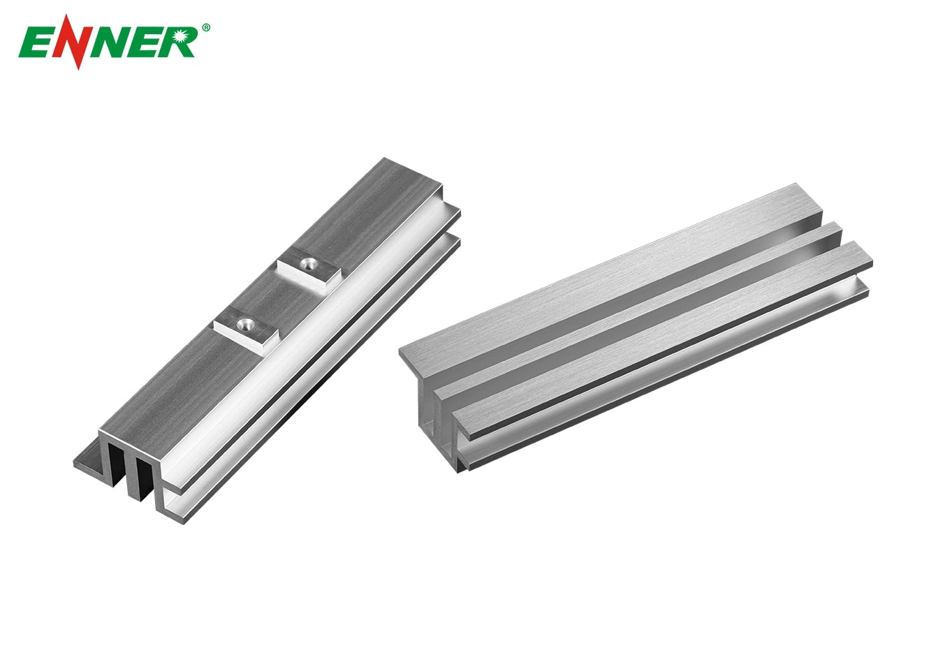
Heat sink geometry also affects performance. Extruded aluminum heat sinks offer configurable profiles with different fin geometries and base dimensions to accommodate application requirements.
The total allowable junction to ambient thermal resistance depends on maximum junction temperature, local ambient temperature, and component power dissipation.
For example, a component dissipating 30 W with a maximum junction temperature of 125°C in a 40°C environment has an available temperature difference of 85°C. This corresponds to a maximum junction to ambient thermal resistance of approximately 2.83 K/W.
This value applies to the complete thermal path, not the heat sink alone.
The complete thermal path includes junction to case resistance, case to sink interface resistance, and heat sink to ambient resistance. Engineers must account for the first two before determining the allowable resistance of the heat sink.
For example, if the total thermal resistance budget is 2.83 K/W, the package resistance is 0.8 K/W, and the interface resistance is 0.3 K/W, the heat sink must achieve approximately 1.73 K/W or lower under the specified conditions.
For additional design considerations, see Enner Group’s heat sink thermal resistance guidance.
Natural convection relies on buoyancy driven air movement, while forced convection uses fans to move air across the heat sink. Forced airflow can improve heat transfer, but its effectiveness depends on air velocity, pressure drop, and flow distribution.
Fin spacing must balance surface area against airflow resistance. Closely spaced fins provide more surface area within a limited footprint but may restrict airflow when the available pressure is insufficient.
The contact between a semiconductor package and heat sink introduces additional thermal resistance. Surface flatness, mounting pressure, interface material thickness, and material conductivity influence heat transfer across this joint.
Thermal grease and gap pads should be selected according to component geometry, electrical insulation requirements, and assembly conditions. Consistent mounting pressure helps achieve predictable thermal performance.
Fin height, thickness, base dimensions, and orientation affect heat transfer and installation compatibility. The required dimensions depend on the thermal target, available space, and cooling method rather than surface area alone.
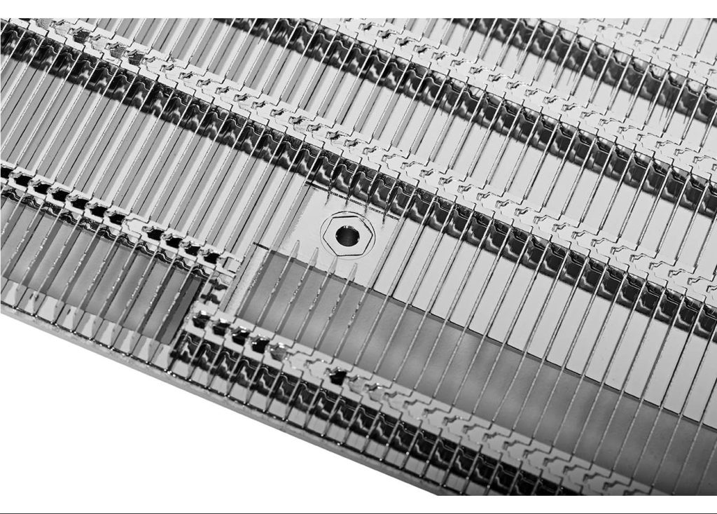
When a compact design requires high fin density, skived heat sinks provide an option for forming thin fins directly from a metal base. Actual performance still depends on airflow and the complete assembly.

Using room temperature instead of the actual enclosure temperature can overestimate the available cooling margin. Unrealistic power estimates can also lead to an undersized heat sink.
Calculations should reflect expected operating loads, nearby heat sources, enclosure ventilation, and the most demanding credible environmental conditions.
Basic calculators may assume heat enters the heat sink uniformly. In practice, concentrated heat sources can create local hot spots, while multiple components sharing a heat sink can influence one another’s temperatures.
These applications may require thermal simulation or a more detailed thermal model to evaluate temperature distribution accurately.
Steady state calculations estimate temperatures after the system approaches thermal equilibrium. They do not fully describe short power pulses, startup loads, or changing operating cycles.
For intermittent loads, engineers may need transient thermal data or time dependent simulation to evaluate peak junction temperatures accurately.
When heat is concentrated in a restricted area, a conventional solid heat sink may struggle to distribute energy across its available fin area. Heat pipe cooling solutions can transfer heat from a concentrated source to a larger cooling area, subject to system geometry, orientation, and heat transport limits.
This approach may be suitable when space constraints or localized heat loads make conventional cooling difficult.

After selecting a candidate heat sink, measure component and heat sink temperatures under representative power loads and ambient conditions. Testing helps identify differences between predicted and actual performance.
Validation should account for mounting conditions, interface materials, airflow, and enclosure configuration. For demanding applications, thermal simulation followed by prototype testing provides a stronger basis for final sizing.
A calculator is useful for preliminary sizing and comparing options. Final designs should be checked against component data, manufacturer performance information, simulation, or physical testing.
Not necessarily. Performance also depends on fin geometry, airflow, heat spreading, and installation orientation. A larger design may occupy more space without delivering the expected improvement.
No. A calculator establishes a thermal performance target, but exact dimensions depend on operating conditions, manufacturing methods, mounting requirements, and available space.
A heatsink calculator establishes the initial thermal requirements for selecting a suitable cooling solution. Accurate sizing also requires realistic operating conditions and performance validation. For customized heat sink designs, contact Enner Group to discuss suitable options.