Newer
How Extruded Heatsinks Improve Thermal Management in Industrial Equipment
This guide explains the key design factors that influence the thermal performance of extruded heatsinks in industrial applications. It covers how material selection, fin geometry, airflow conditions, and cooling methods directly impact heat dissipation efficiency and overall system reliability.
By understanding these core elements, engineers can optimize heatsink design to improve thermal management, reduce operating temperatures, and ensure stable performance in high-power industrial equipment.
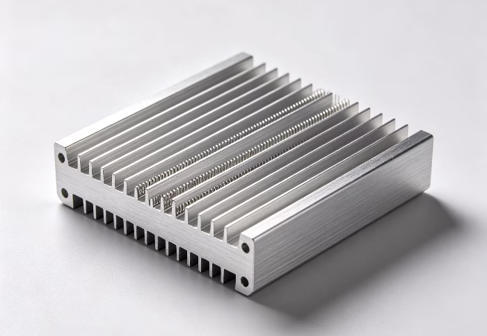
An extruded heatsink is manufactured using the aluminum extrusion process. During this process, heated aluminum billets (typically 6063 aluminum alloy) are forced through a precision steel die under high pressure. This creates a continuous profile with a specific cross-sectional shape, which is then cut to the desired length.
The defining characteristic of an extruded heatsink is its monolithic construction. Because the base and the fins are formed from a single piece of metal, there are no mechanical joints or thermal interface materials between the base and the fins, which provides superior thermal conductivity.
Extruded heatsinks operate based on the principles of thermal conduction and thermal convection. The process follows these steps:
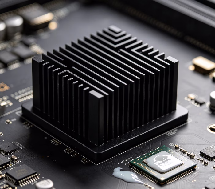
Thermal Conduction: The base of the heatsink is placed in direct contact with the heat source (e.g., a CPU, MOSFET, or LED). Heat is transferred from the component through a Thermal Interface Material (TIM) and into the heatsink base. Because of the excellent thermal conductivity of aluminum, the heat travels rapidly from the base into the vertical fins.
Surface Area Expansion: The primary function of the fins is to maximize the effective surface area. Since heat dissipation occurs at the boundary between the metal surface and the air, increasing the surface area allows more air to absorb heat simultaneously.
Thermal Convection: As air comes into contact with the heated fins, it gains energy. This warmed air becomes less dense and rises (natural convection), or it is pushed away by fans (forced convection). This continuous cycle replaces warm air with cooler ambient air, effectively moving heat away from the electronic components and into the surrounding environment.
| Feature | Benefit |
| Monolithic Design | Eliminates thermal resistance caused by joints or adhesives. |
| High Durability | Aluminum is resistant to corrosion and does not degrade over time. |
| Cost-Effectiveness | Highly efficient for mass production; low tooling and material costs. |
| Design Flexibility | Dies can be customized to create various fin geometries and densities. |
The cooling efficiency of an extruded heatsink is determined by how well it transfers heat from the source to the ambient air. Here are the primary variables:
Total Surface Area: More surface area equals more cooling power.
Fin Density: High density increases cooling but restricts airflow.
Fin Height/Thickness: Taller fins add area but increase the distance heat must travel.
Complex Shapes: Serrated or flared fins create turbulence, which improves heat transfer efficiency.
The contact point between the heat source and the heatsink is critical. Any air gap acts as an insulator.
High-quality thermal paste or pads are essential to fill microscopic gaps, drastically reducing thermal resistance and ensuring an efficient “heat highway.”
Natural Convection: Requires wider fin spacing to allow air to rise naturally (the “chimney effect”).
Forced Convection: Using fans allows for tighter fin spacing and higher cooling capacity by overcoming flow resistance.
Base Thickness: A thicker base distributes heat laterally before it reaches the fins, preventing localized “hot spots.”
Material Purity: High-purity aluminum (e.g., 6063-T5) is preferred for its superior thermal conductivity compared to lower-grade alloys.
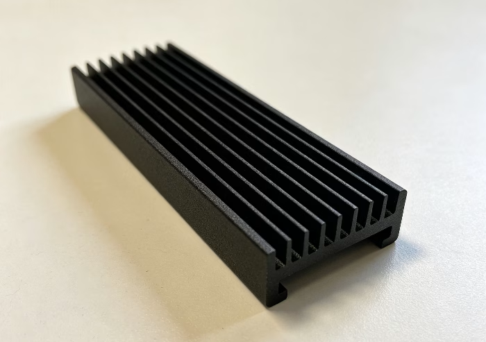
Anodization: Adding an anodized finish (especially black) increases surface emissivity, which helps dissipate heat via radiation—beneficial in low-airflow environments.
Optimizing a heatsink requires balancing thermal conductivity, structural integrity, and airflow dynamics. The goal is to minimize thermal resistance from the heat source to the ambient air.
Aluminum (6063-T5): The industry standard due to its excellent strength-to-weight ratio, ease of extrusion, and corrosion resistance. It offers a balance of affordability and sufficient thermal conductivity (~200–210 W/m·K).
Copper: Used in high-performance applications. With significantly higher thermal conductivity (~385–400 W/m·K) than aluminum, it is often embedded into an aluminum base (heat pipe or copper slug) to handle localized “hot spots” where heat density is extreme.
The geometry of the fins determines how effectively heat is rejected into the environment.
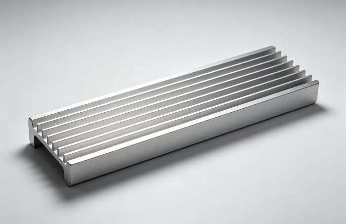
Fin Pitch (Spacing): * Wide Pitch: Essential for natural convection, as it reduces air resistance and allows air to move freely through buoyancy.
Tight Pitch: Ideal for forced convection (using a fan). It maximizes surface area, but the air must be pushed under pressure to overcome the friction between the fins.
Fin Shape: * Straight Fins: The most common, cost-effective design for simple airflow patterns.
Flared/Serrated Fins: Disrupt the laminar airflow to create turbulence. This “breaks” the boundary layer of stagnant air clinging to the fin surface, significantly increasing heat transfer efficiency.
Aspect Ratio (Height vs. Thickness): A high aspect ratio (tall, thin fins) provides maximum surface area but can lead to structural weakness or “fin tip” cooling issues where the end of the fin is much cooler than the base. Engineers must ensure the fin is thick enough to conduct heat effectively to its tip.
To achieve peak performance, you must match the design to the environment:
| Application | Best Material | Best Fin Strategy |
| Passive Cooling | Aluminum | Low density, wide pitch |
| Active Cooling (Fan) | Aluminum + Copper base | High density, thin fins |
| High Heat Density | Copper | Integrated heat pipes/vapor chambers |
By selecting the correct alloy and tailoring the fin geometry to your specific airflow conditions, you can significantly lower operating temperatures and extend the lifespan of your electronic components.
The performance of an extruded heatsink is not inherent; it is defined by the environment in which it operates. The relationship between your cooling method and the heatsink’s design is the deciding factor in effective thermal management.
Natural convection relies entirely on the buoyancy of air—heated air rises, creating a vacuum that pulls in cooler air.
Design Requirement: Heatsinks designed for passive cooling must have wider fin spacing. If fins are too close together, the friction (air resistance) prevents the air from circulating effectively, causing a “stagnant air zone.”
Orientation: The heatsink must be mounted vertically to facilitate the “chimney effect.” Horizontal mounting significantly reduces performance as it blocks the natural upward path of heated air.
Forced convection uses external energy (fans or blowers) to push air through the heatsink fins.
Design Requirement: Because the fan provides pressure, you can utilize high-density, thin-fin designs. This maximizes the surface area in a compact footprint.
Static Pressure: It is not just about airflow (CFM); it is about static pressure. If your fins are very dense, you need a fan capable of generating high static pressure to force air through the narrow channels rather than letting it deflect off the front of the heatsink.
Airflow Path: Ensure there is a clear path for air intake and exhaust. Mounting a heatsink inside a sealed, stagnant enclosure will lead to thermal throttling, regardless of how efficient the heatsink is, because the ambient air temperature inside the box will quickly reach equilibrium with the heat source.
Flow Impedance: Every obstruction—such as cables, other components, or tight enclosure walls—increases flow impedance. Always aim to place the heatsink in the direct path of the system’s primary airflow intake.
Boundary Layer: In forced convection, air tends to “stick” to the fin surface (the boundary layer), acting as an insulator. Turbulence-inducing features, such as interrupted or jagged fins, help break this layer and force the cooler air into direct contact with the metal.
In industrial environments, off-the-shelf heatsinks often fail to meet the performance and space demands of specialized hardware. Custom aluminum extrusions provide a precision-engineered alternative, allowing you to optimize thermal resistance, structural integrity, and physical fit for your specific application.
Performance Tuning: Adjust fin density, height, and thickness to perfectly match your airflow—whether passive or forced-air—maximizing heat dissipation.
Seamless Integration: Incorporate mounting holes, standoffs, and precision-machined bases directly into the profile. This reduces assembly labor and ensures optimal contact pressure with heat sources.
Environmental Durability: Beyond standard aluminum, utilize specialized alloys and finishes like hard-coat anodizing to resist corrosion and provide necessary electrical insulation in harsh environments.
Space Optimization: Tailor the profile shape to fit irregular chassis cavities, maximizing cooling surface area without increasing the overall device footprint.
To ensure a successful thermal strategy, consider these three pillars:
Thermal Path Efficiency: Minimize the resistance between your component and the ambient air by matching base flatness to your Thermal Interface Material (TIM).
Airflow Optimization: Design fin orientation to support your system’s cooling method, ensuring minimal air resistance and maximum thermal transfer.
Structural Utility: Treat the heatsink as a structural element. A custom extrusion can act as a rigid chassis component, built to withstand the vibration and shock common in industrial machinery.
Selecting the optimal heatsink requires balancing thermal performance with mechanical constraints and budget. To find the right solution for your project, focus on these four critical selection criteria:
First, determine the Total Heat Load (W) your components generate. Calculate the maximum allowable case temperature and compare it against the ambient temperature of your environment. This defines your required Thermal Resistance ($\theta$). A heatsink with a lower thermal resistance will be more efficient but typically larger or more complex.
Natural Convection: If your system relies on passive cooling, choose a design with wider fin spacing to allow air to rise freely through the heatsink.
Forced Air: If you are using fans, you can select higher fin densities. However, ensure the fin length and density do not create excessive backpressure, which can diminish fan efficiency.
Evaluate your enclosure’s physical footprint. Custom extrusions allow you to tailor the width, length, and height to fit tight spaces. Additionally, consider the mounting method:
Pre-machining: Can the profile accommodate integrated clips, captive fasteners, or PEM nuts to simplify assembly?
Base Flatness: Ensure the mounting surface of the heatsink meets the flatness requirements of your Thermal Interface Material (TIM) to prevent air gaps that lead to localized overheating.
Don’t overlook the operational setting. If your device will be exposed to moisture, chemicals, or high voltage:
Finishes: Anodizing is essential for corrosion resistance and can be specified as “hard-coat” for extra durability or dielectric strength.
Structural Load: If the heatsink serves as a structural part of your chassis, select alloys (such as 6063 vs. 6061) that provide the necessary rigidity to withstand vibration or mechanical impact.
Extruded aluminum heatsinks are the cornerstone of industrial thermal management, offering a reliable, cost-effective, and highly customizable way to dissipate heat through optimized fin geometry and material selection. By precisely balancing airflow dynamics, thermal interface integrity, and structural needs, these components ensure the long-term stability and performance of high-power electronics.
At Ennergroup, we specialize in engineering bespoke extruded solutions tailored to your project’s unique space, environmental, and thermal requirements. Whether you need to maximize cooling in compact spaces or require rugged, corrosion-resistant designs for harsh industrial settings, our expertise ensures your systems remain cool, efficient, and reliable.
What is an extruded heatsink design guide used for?
It helps engineers understand how design factors such as material, fin structure, and airflow impact thermal performance in industrial applications.
What are the most important factors affecting heatsink performance?
Key factors include material thermal conductivity, fin geometry, airflow conditions, heat load, and available installation space.
Why is fin design important in extruded heatsinks?
Fin design directly affects surface area and airflow efficiency, which determines how quickly heat can be transferred away from electronic components.
How does material selection impact thermal performance?
Aluminum alloys are commonly used because they offer high thermal conductivity, low weight, and good corrosion resistance, improving overall heat dissipation.