



















Newer
High-Performance Heat Sinks: Thermal Resistance & Tolerances
Modern high performance computing platforms generate immense thermal density within small silicon areas. Managing these heat loads is critical to preventing thermal throttling, maintaining high boost frequencies, and ensuring long term hardware reliability. Among various thermal management strategies, heat pipe cooling systems remain the standard for balancing passive reliability, structural simplicity, and cost effectiveness.
Whether you are configuring custom thermal assemblies for high density servers or selecting a cooling setup for commercial workstations, understanding the underlying phase change thermodynamics, wick mechanics, and hardware limitations is essential.
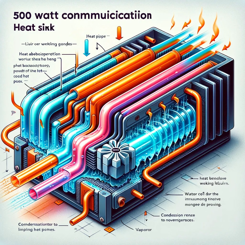
To appreciate why this technology dominates the electronics sector, one must first look at the underlying physical mechanics that drive phase change thermal transfer. A heat pipe is a sealed, high purity copper tube containing a small amount of working fluid, usually deionized water, operating under a partial vacuum.
The thermal transfer process relies on a continuous phase change cycle occurring within three primary internal zones:
Liquid return relies entirely on capillary forces generated by an internal porous wick structure bonded to the inner copper wall. As the liquid condenses at the cold end, capillary pressure pulls the fluid back to the evaporator section without requiring any mechanical pumps or moving parts.
Having established the foundational mechanics of liquid vapor cycles, let us examine the key mechanical and structural choices that dictate real world thermal performance.
Not all heat pipe assemblies perform equally. Small variations in mechanical construction, baseplate contact methods, and fin arrangements create substantial differences in heat transfer rates.
The total heat transport capacity depends heavily on the internal cross sectional area of the vapor core. Standard 6 millimeter heat pipes typically carry between 25 and 35 Watts of thermal load each. Upgrading to 8 millimeter heat pipes expands the internal vapor space, increasing individual thermal capacity up to 50 to 60 Watts per tube. An array of six 6 millimeter pipes generally provides better thermal distribution across a wide fin stack than four 8 millimeter pipes due to increased contact area.
Direct contact designs flatten the bottom of the copper tubes to touch the CPU heat spreader directly. This layout eliminates an extra thermal interface layer, making it cost effective and responsive for localized hot spots. However, solid copper baseplates use a precision machined, nickel plated copper block to bridge the gap between the CPU and the heat pipes. This approach delivers uniform heat distribution across all pipes, which is ideal for multi chiplet processor architectures.
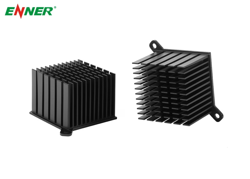
Moving thermal energy from the heat pipes into the surrounding environment requires a well designed aluminum fin stack. Denser fin spacing offers greater surface area but increases airflow resistance, demanding higher static pressure fans. Wider fin pitch reduces static pressure requirements, allowing for quieter operation at lower fan speeds.
With an understanding of these physical dimensions, we can now evaluate how traditional heat pipe air coolers perform when measured against liquid cooling alternatives.
Engineers and system builders frequently compare passive heat pipe assemblies against active All In One liquid loops to determine long term operational value.
| Metric | Heat Pipe Air Cooler | AIO Liquid Cooler |
| Failure Points | Fan bearing only | Pump motor, fluid permeation, fans |
| Leakage Risk | Zero | Low to Moderate |
| Lifespan | 10+ Years | 3 to 5 Years |
| Maintenance | Dust removal only | Full replacement upon pump failure |
| Cost Efficiency | High | Moderate |
For modern CPUs operating at high continuous wattage, liquid coolers with large radiators provide higher initial thermal mass. However, dual tower heat pipe designs with 6 to 8 pipes comfortably handle continuous thermal loads up to 250 Watts, keeping operating temperatures well within safe limits.
Heat pipe systems contain no active mechanical fluid pumps. While liquid coolers carry risks of pump degradation, fluid evaporation, and potential seal leaks over extended use, a heat pipe structure operates indefinitely. The only moving part is the cooling fan, which can be swapped easily without dismantling the thermal assembly.
While raw cooling performance and reliability drive general purchasing decisions, physical mounting angles and internal wick choices introduce hidden variables that can degrade performance if overlooked.
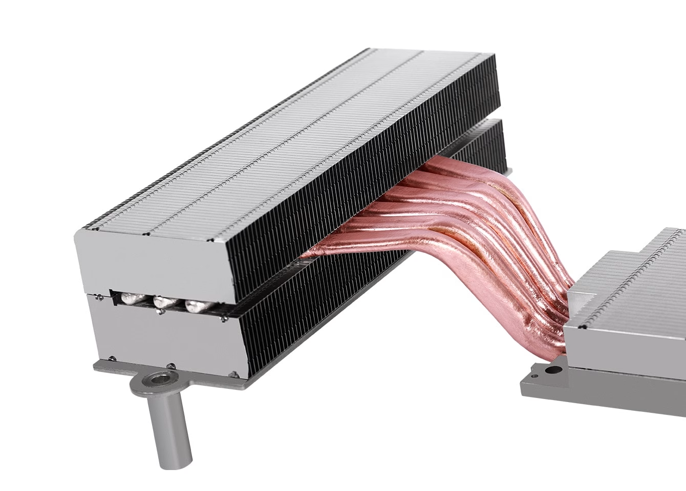
Standard technical guides often assume heat pipes perform identically regardless of chassis placement. In reality, gravitational forces and internal wick construction play a massive role in real world thermal dissipation.
When a chassis is oriented vertically, heat pipes must frequently push condensed liquid upward against gravity from a lower condenser back to a higher evaporator. If the capillary force generated by the internal wick is weaker than the gravitational pull, liquid reflux slows down. This creates dry out conditions at the evaporator, causing CPU temperatures to spike under sustained workloads.
The internal wick design determines how effectively a heat pipe overcomes gravitational resistance:
When a CPU experiences rapid thermal spikes, the heat flux at the evaporator can exceed the capillary limit of the wick. Liquid cannot return quickly enough to replace the evaporating fluid. This forms a continuous vapor barrier along the inner wall, causing thermal resistance to jump dramatically. Selecting properly rated heat pipe assemblies prevents this bottleneck.
Knowing how internal structures behave under thermal stress allows us to lay out clear practical guidelines for selecting and installing these assemblies.
Selecting the correct assembly requires matching thermal capacity against processor power profiles while double checking mechanical clearance.
Always choose a thermal assembly rated above the peak boost power output of your processor:
Before finalizing a design, verify three critical dimensional boundaries:
Apply a small, uniform amount of thermal compound across the CPU surface. Tighten the mounting screws in a diagonal cross pattern incrementally. This distributes clamping force evenly, preventing socket warping and ensuring minimal bond line thickness across the baseplate.
When commercial off the shelf coolers cannot satisfy custom server configurations, industrial equipment specs, or unique mechanical requirements, specialized manufacturing services become essential.
For specialized industrial, telecommunications, and high density computing projects, standard consumer products are often insufficient. Dedicated engineering and custom fabrication are required to meet tight space constraints and extreme heat dissipation targets. As a specialized thermal management manufacturer, Ennergroup delivers custom cooling solutions designed for demanding electronic and industrial environments.
Heat pipes are hermetically sealed copper systems without moving parts. Under normal operational temperatures, they do not suffer from fluid loss or vacuum degradation, operating reliably for 10 to 15 years or more.
No. Heat pipes are designed to withstand internal vapor pressures far above standard operating limits. Even if a CPU reaches its upper temperature limits, internal pressures remain safely within the structural tolerances of the copper wall.
For mid range processors drawing between 65 and 120 Watts during gaming, a well designed 4 heat pipe cooler paired with a 120 millimeter fan provides ample thermal headroom.
Yes. Fans should always be installed in a push pull layout blowing air in a single direction toward the chassis exhaust vents. Reversing one fan creates opposing airflow pressure, trapping heat inside the fin array.
Heat pipe thermal systems remain an extremely reliable and cost effective choice for managing modern CPU heat loads. By combining phase change thermodynamics with capillary action, these systems deliver high performance cooling without the mechanical failure risks associated with liquid pumps. Evaluating structural factors such as wick construction, mounting orientations, and baseplate designs ensures long term system stability under heavy workloads.
If your project requires custom thermal designs, rapid prototyping, or high volume industrial production, contact the engineering team at Ennergroup to discuss your technical specifications and request a customized cooling evaluation.