Customizing a heat sink isn't just about fitting metal to a component. It's about creating a thermal solution that meets specific technical, environmental, and structural demands. From compact wearables to industrial controllers, each project comes with its own set of constraints. The process involves far more than shape and size—it balances material science, airflow dynamics, and mechanical integration. Here's how that process unfolds, step by step.
Everything starts with information. The more complete the input, the more accurate the thermal solution.
At the core is the heat load. You need to define how much power the device will dissipate under normal and peak conditions. This value—often expressed in watts—drives the rest of the design. But thermal output is just the beginning.
Ambient temperature is just as important. A device running indoors at 25°C needs a different approach than one mounted inside an enclosure exposed to 50°C ambient air. If the system is fan-cooled, airflow rate and direction need to be known. If passive cooling is required, that limits geometry and increases the demand for materials with high conductivity.
The form factor matters too. Some applications allow for tall fin structures, while others have only a few millimeters of vertical clearance. Mounting holes, connector locations, nearby components—all of them affect where and how a heat sink can be attached. And sometimes, thermal interface pressure constraints mean the sink can't be clamped too tightly, which influences material flatness and base stiffness.
Additional questions arise if the application involves movement or vibration. Will the part be subject to shock loading? Should the design consider stress isolation or mounting via spring clips? Is the operating orientation fixed, or will it change in the field? These all impact the selection of base geometry, fin orientation, and structural reinforcement.
This phase should not be rushed. Oversights at this point usually lead to costly redesigns later.
Once all the data is in place, a thermal engineer creates a design concept. This is more than just CAD modeling—it's a thermal balancing act.
Material selection comes first. Aluminum is often chosen for its balance of cost, machinability, and conductivity. But for extremely high-performance needs, copper or hybrid solutions may be proposed. These might include a copper base with aluminum fins or embedded vapor chambers to manage hotspot dissipation.
The engineer then selects the heat spreading mechanism. If the heat source is uniform and base area is large, a solid plate may be enough. But for point-source heat or uneven loading, vapor chambers or heat pipes are added to spread heat before it reaches the fins.
Fin geometry follows. Taller, thinner fins increase surface area but add resistance to airflow. In passive systems, this might hurt natural convection. In forced-air setups, tightly packed fins might cause back pressure if airflow isn't strong enough.
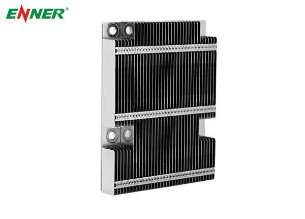
Not all fin structures are created the same way. Skived Heat Sinks, for example, are carved from a solid metal block using precision blades, resulting in tightly spaced fins with excellent thermal conductivity. They're often used in telecom or industrial systems where density and thermal performance must coexist.
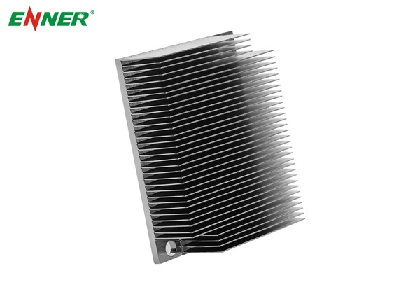
Other projects may call for Zipper Fins Heat Sinks, which are assembled from interlocked stamped fins, allowing greater flexibility in fin count and direction. These are especially effective in confined spaces with directional forced airflow, such as embedded or power supply units.
Simulations are usually run at this point. These models use CFD (computational fluid dynamics) to estimate how heat will move through the system and how air will flow around the sink. The data helps spot weaknesses—like stagnant airflow zones or insufficient base spreading—before any metal is cut.
At the end of this step, the client typically receives drawings, thermal simulations, and sometimes multiple design options with performance and cost differences noted.
Theory only goes so far. Physical testing verifies the assumptions made during design.
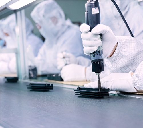
A prototype is created, often using CNC machining or soft-tool extrusion. Surface finishes are typically not final at this point. Instead, the goal is to test basic performance and fit.
Thermal resistance is measured under load. Sensors monitor the temperature at the base, the heat source, and the fin tips. Results are compared to the simulation. If the real-world performance deviates significantly, the model is reviewed. Sometimes it's due to airflow not behaving as expected. Other times, it's material inconsistency or mounting issues.
Fit checks are also critical. Even if the thermal performance is strong, poor alignment, awkward mounting, or clearance interference can make the design unworkable. Engineers may suggest changing the mounting hole pattern, adjusting fin orientation, or modifying the base contour.
Some prototypes include heat pipes or vapor chambers. These must also be tested for internal pressure stability and orientation sensitivity. In passive systems, it's important to verify that condensate returns properly under gravity.
Designs are often revised at this stage—not because they failed, but because they can be optimized. Small changes can shave off cost, reduce weight, or improve ease of installation.

Once the prototype performs well, it moves toward finalization. This is where engineering meets manufacturability.
Drawings are locked. Tolerances are defined. Surface treatments are selected based on environmental exposure, electrical requirements, or visual standards. Anodizing, chromate conversion, and nickel plating are common options. Each has trade-offs between corrosion resistance, thermal emissivity, and cost.
Thermal interface material (TIM) choices are finalized here too. Options include thermal pads, pastes, phase-change materials, or pre-applied films. These materials affect assembly time, field maintenance, and long-term performance.
For volume production, DFM (design for manufacturing) analysis is done. Can the part be extruded and then machined? Should it be fully CNC'd from billet? If heat pipes are used, are their bends and joints compatible with automation? For multi-fin structures, how are the fins bonded or attached? All of this affects tooling costs, lead times, and consistency.
If performance is critical, a pre-production batch may be run. This verifies repeatability, especially if multiple thermal modules need to meet tight tolerances. Measurements of surface flatness, thermal resistance, and mounting accuracy are used to ensure stability.
Production begins once everything is approved—but quality control doesn't stop.
Each unit may undergo basic inspections: dimensional checks, surface finish review, and fit assessments. In high-volume applications or regulated industries, sampling plans and process capability studies are used. Key dimensions like base flatness or hole alignment are often measured with precision equipment.
For parts involving heat pipes or vapor chambers, leak testing and pressure verification are performed. Some vendors apply barcode traceability so that every component can be tracked back to a specific production batch or material lot.
Logistics also matter. Fin structures can be fragile. Custom packaging is often created to protect products in shipping. Some customers receive pre-assembled thermal modules, while others get bare heat sinks with accessories packaged separately.
Lead times vary depending on the complexity. Simple extruded designs with basic machining may be produced in weeks. More complex designs involving skived or zipper fins, heat pipes, or integrated machined enclosures may take longer, especially if tooling or special coatings are required.
If demand is ongoing, production scaling and reorder planning become part of the support process. Some suppliers offer blanket order programs or inventory stocking services to ensure timely delivery without overstock.
A custom heat sink isn't a commodity—it's a targeted solution. Each step in the process, from understanding thermal loads to refining geometry and verifying results, plays a role in achieving performance goals. There's no one-size-fits-all in thermal design, and that's what makes customization essential for modern electronics.
If you're seeking a partner to support your custom thermal needs with full-cycle design and manufacturing capability, reach out via [email protected] for expert guidance.
 Leave message
By continuing to use the site you agree to our privacy policy Terms and Conditions.


 Crystal Xi


